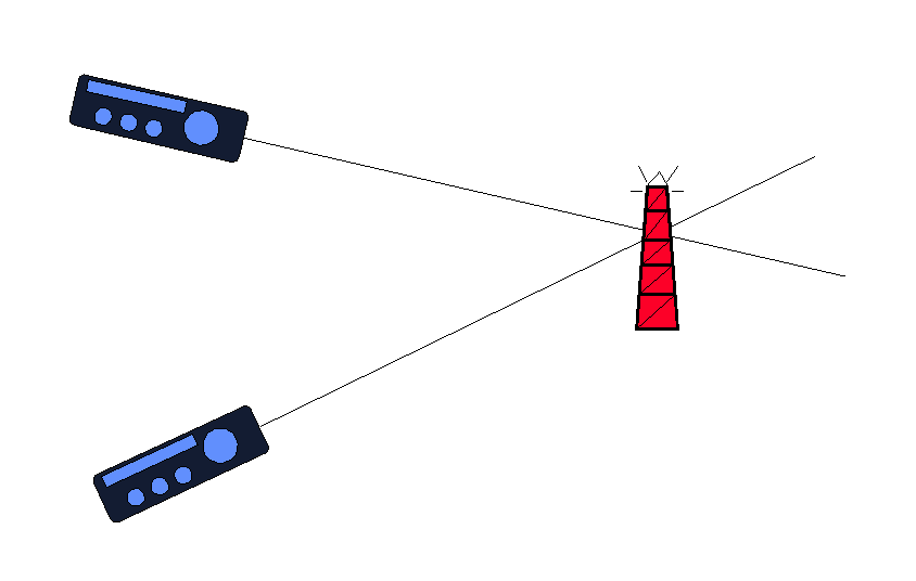
What is Amateur Radio Direction Finding?
In general, radio direction finding (RDF) is used for two purposes:
-
To find your location when you know the locations of radio transmitters that
your can hear on a radio receiver. This is the most common use of RDF and
is used by aircraft and ships to determine their location from special radio
beacons whose positions are shown on charts. The calculations are performed
on the aircraft or ship.
-
To find the unknown location of a radio transmitter that your can hear on
a radio receiver given that you know your own location. This is also used
for locating the position of ships and aircraft but in this case the aircraft
or ship transmits to a number of ground stations which cooperate to determine
the location which is passed to the aircraft or ship by radio. It is also
used to locate Emergency Position Indicating Radio Beacons (EPIRBs) often
fitted to liferafts. It is this approach that is used in ARDF, the idea is
that competitors locate hidden transmitters.
How does RDF Work?
Radio Direction Finding relies on the "fact" that radio signals travel in
straight lines. You need a radio receiver with a directional aerial, that
is, an aerial which receives better in some directions than others. If you
have a portable broadcast radio receiver it contains a directional aerial
known as a ferrite rod. Try this, at least up to step 4:
-
Tune in a local radio station on medium wave.
-
Slowly rotate the radio about a vertical axis.
-
There will be two directions where the signal fades away. Beware, these nulls
may be very narrow.
-
When located in the null the aerial in the set is pointing along a line joining
your location and the location of the transmitter. The aerial is usually
along the long axis of the radio when it is standing in its normal way.
-
You can tell what direction this line is by sighting along the set with a suitable
compass.
-
Take the reading from the compass and plot it onto a map through the point
representing your position. The line goes through the location of the
transmitter.
-
Go to a different location some distance away from the line of the above
bearing and repeat steps 1 - 6. The two bearings cross where the transmitter
is located.
Steps 1-5 are known as "taking a bearing." Step 6 is known as "plotting the
bearing."
 That is the theory!
In practice things are more difficult. That is the theory!
In practice things are more difficult.
-
Radio signals get "bent" by
-
nearby wire fences and overhead cables
-
underground cables and pipes
-
hills and valleys
-
large buildings, especially metal ones
-
the coast
-
variations in ground conductivity
-
variations in the ionosphere, particularly at night
-
The compass can be affected by
-
magnetic variation (this is predictable)
-
magnetic deviation (nearby magnetic materials, e.g. cars, parts of the radio
set)
160 metres is an amateur radio band (ham band). On 160 metres the transmitters
are at frequencies similar to those of mediumwave broadcast stations. Mediumwave
is 525 to 1625 kHz; 160 metres is 1810 to 2000 kHz.
2 metres is another amateur radio band which is more like the VHF broadcast
band. VHF broadcast is 88 to 108 MHz; 2 metres is 144 to 146 MHz.
Fortunately there are methods to determine which direction along the line
is towards the transmitter. On 160 metres an omnidirection sense aerial is
switched in as well as the directional aerial; this removes the null in one
direction. On 2 metres the directional aerial is usually a small Yagi antenna
which has a peak in one direction. On 160 metres the accuracy of bearings
is typically +/- 5 degrees but errors up to 30 degrees can happen. On 2 metres
things are much worse because the signals are more easily affected by buildings
and terrain which can result in errors up to 180 degrees.
To actually locate the transmitter you have to repeat the process of taking
and plotting bearings as you "home in" closer to it.
|

